Directive Engine
Pixels to atoms — a directive engine that bridges detection and execution for field teams. Deviations in, installer-language directives out, with pass/fail verification of closure.
Open live demo · Repository · Contact
Problem
When something is off in the field, the hardest part is not detecting it — it’s expressing the correction in a field-executable format that’s:
- Unambiguous — a directive an installer can execute with a wrench. “Translate +3.2mm along slot S2”, not “translate +3.2mm in part-frame Y.”
- Constrained — respects what the part is physically allowed to do: named pivots, slots, and indexed bolt patterns, not abstract axes.
- Verifiable — pass/fail closure check after adjustment. Did the residual drop inside tolerance?
Inputs
Two inputs feed the engine: a nominal model (design intent — 3D geometry plus named features) and an as-built scan (field reality — point cloud or survey data).
Data format: JSON contracts for as-built poses, constraint metadata (joints, slots, indexed patterns), and directive outputs. Schemas live in the repo; the engine output is identical with or without named features declared — features are pure presentation metadata.
Calibration and constraints
The engine operates on a calibrated frame: as-built poses expressed in a shared world coordinate system, with each part’s pose represented as T_world_part (translation + quaternion). The v0.2 demo runs on the synthetic toy_facade_v1 fixture — a 12-panel subsection with deviations designed to exercise the contract end-to-end.
Worst deviation on the fixture: ~8mm before apply, <1mm after apply (within the ±2.0mm tolerance). The geometry and deviations are synthetic — designed to exercise the contract — but the engine math (DOF projection, indexed rotation quantization, status logic) is real and unit-tested. The same primitives generalize to larger installs.
Each part declares its kinematic features — the things an installer can actually adjust. The engine projects raw deviations onto these features, so corrections come out in the vocabulary of the hardware, not abstract axes.
Allowed motion: pivot about joint J1, slide along lateral mounting slot S2, and rotate to one of four discrete index positions on bolt pattern P3. Everything else is held by the structure. Corrections that don’t fit are clamped or blocked — never silently rounded.
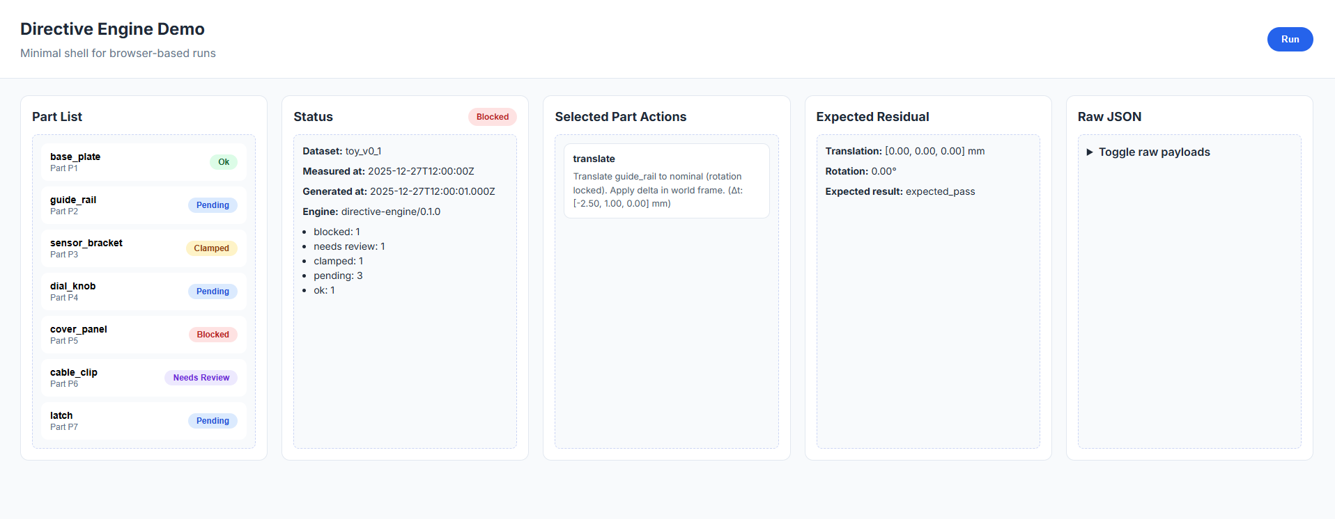
Action format — directive card
The engine emits directive cards — structured correction instructions in installer language:
constraints.jsonpending → ok within toleranceThe mapping from engine math to physical features happens in src/presentation/format-directive.ts; the engine stays generic, the language stays installer-facing.
Verification loop
The live demo walks through the loop in five beats — detection, constraint, directive, apply, verify — on the synthetic toy_facade_v1 fixture. Try it on desktop or mobile: open live demo · demo walkthrough.
- Detection — as-built scene loads. Panels glow yellow or red where deviation exceeds tolerance.
- Constraint — camera dollies to the worst panel. Allowed DOF surface as named features.
- Directive — engine emits the correction as an installer-language card.
- Apply (simulated) — panel animates to corrected pose. Status flips
pending → ok. - Verify — camera returns to the wide shot. Before/after metric closes the loop.
Artifacts
Live demo · Repository · Demo walkthrough
Run it on your own scan
The repository ships with a small CLI that runs the engine against a real point cloud. It accepts an ASCII PLY or XYZ scan plus a nominal-parts JSON describing the part geometries, then prints the resulting directives in human-readable form to the console. The committed example files in examples/ make this reproducible without any setup beyond cloning, and the end-to-end test suite exercises the same path against those files.
git clone https://github.com/barnes-ngb/directive-engine
cd directive-engine && npm install
npx tsx scripts/ingest-pointcloud.ts examples/minimal-scan.ply examples/minimal-parts.json
Expected output:
Parsed 20 points from examples/minimal-scan.ply
  P-01: t=[0.03, 500.00, 0.00]mm  confidence=70.0%
  P-02: t=[506.00, 500.00, 0.00]mm  confidence=70.0%
  P-01: No adjustment required (within tolerance). Status: ok. Tolerance: ±5.0mm.
  P-02: Translate -6.0mm along part-frame X. Status: pending. Tolerance: ±5.0mm.
Same primitives the demo uses, different input format. An in-browser interactive version is a planned next iteration; the CLI is the present way to verify the engine works on real input.
Why this generalizes
The primitives — pose as T_world_part with a quaternion, DOF projection onto declared kinematic features, indexed-rotation quantization, tolerance clamping, before/after verification — are domain-agnostic. The directive engine is the generation half of the loop (deviation → instruction). For the capture half (as-built reality → deviation) in an aerospace-flavored deployment, see SurveyLink, a real-time link between as-designed models and as-built field data.
Roadmap
- Real scan-data ingestion on top of the existing contract
- Step ordering / dependencies (anchors → part → verification)
- Confidence scoring with
needs_reviewflags surfaced in the UI - Tolerance heatmaps to spot systemic drift across a facade
- AR overlay as an output target — not the core product