Pixels to atoms: the missing layer in fabrication
The fabrication industry has spent thirty years building software for design and almost nothing for execution. A look at the missing translation layer.
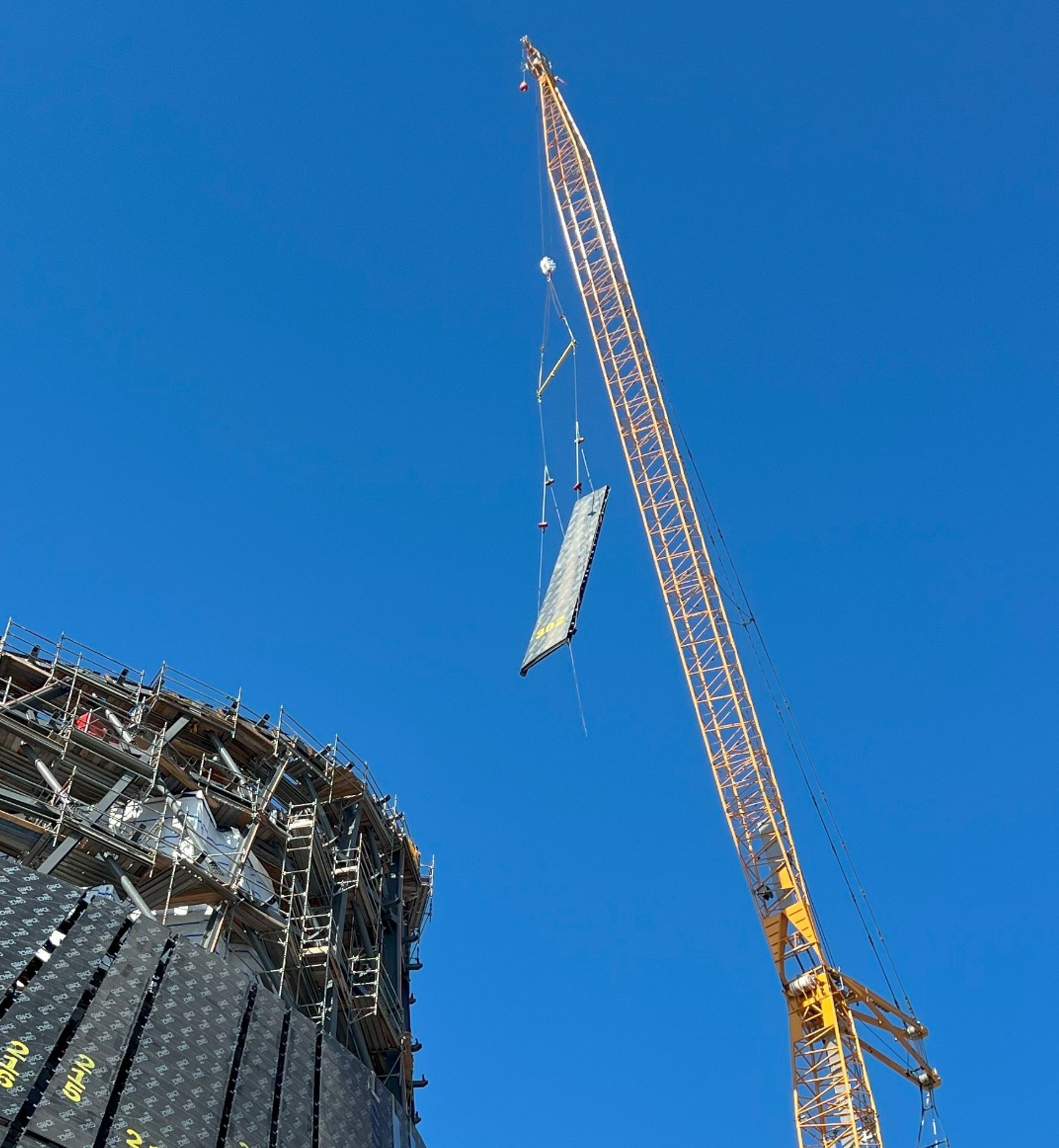
A panel arrives at the job site. The drawing says it goes here. The four bolts go through these holes. The crew lifts it, brings it to the wall, and the holes don’t line up.
This happens. It always happens. Not because anyone made a mistake. The panel was fabricated to spec, the wall was built to spec, the model says they should fit. But the model assumes the wall is perfect. The wall isn’t. It’s eight millimeters off in two places. The structure has settled since the drawings were issued. The column the panel attaches to has a small twist in it from a thermal cycle three months ago.
So the crew has a panel that won’t fit. The foreman calls the office. The office tells him to wait. An engineer eventually drives out, takes measurements, goes back to the office, modifies the panel, sends it to the shop, the shop modifies it, sends it back. Three days have passed. Three days where everyone else on the floor is waiting on this one panel.
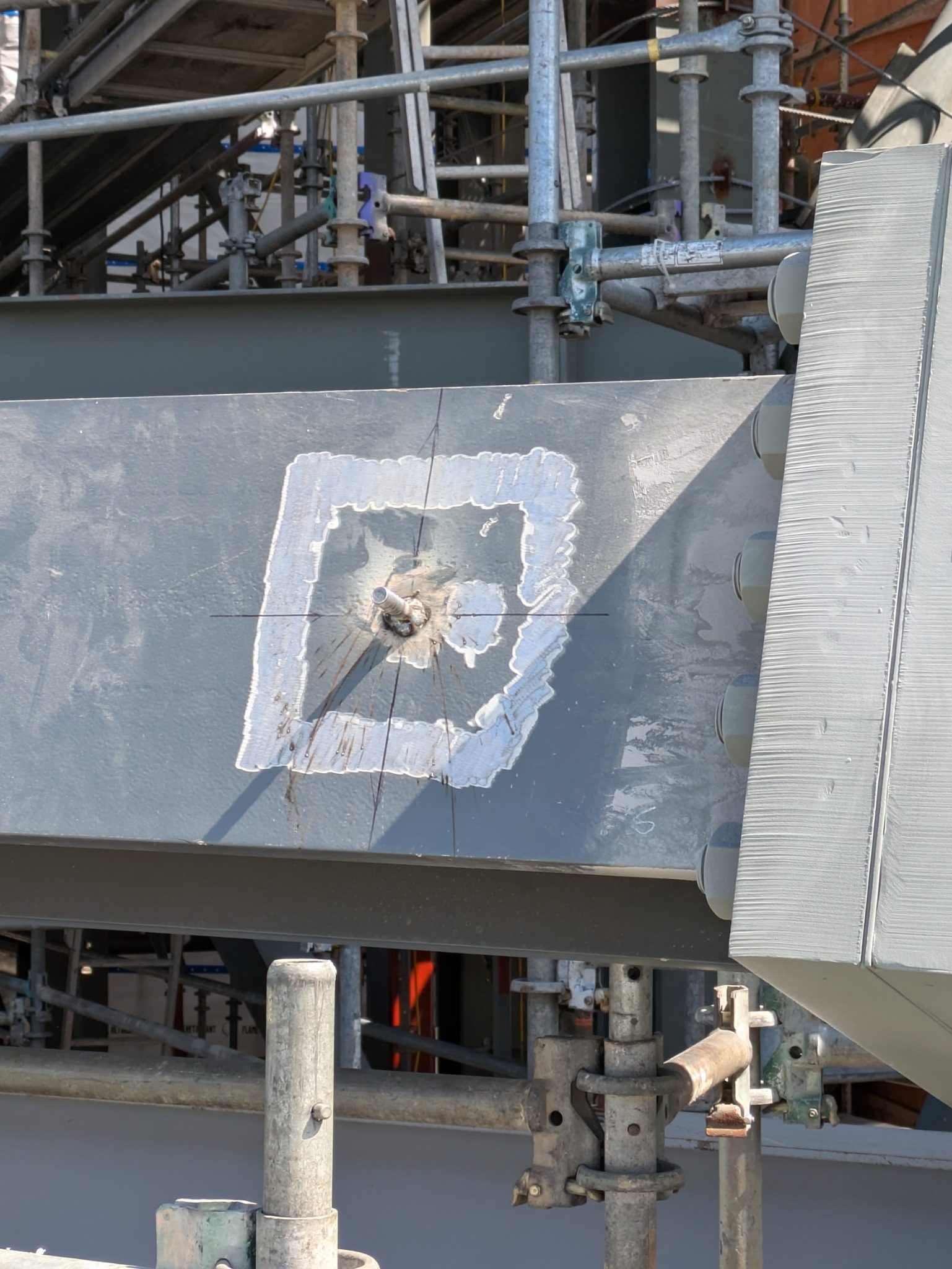
Or, in the version I’ve watched happen, the crew finds a way. Someone gets out a grinder. Someone elongates a hole. The panel goes up, but the as-built doesn’t match the model anymore. Nobody updates the model. The next panel hits the same problem. The cycle continues.
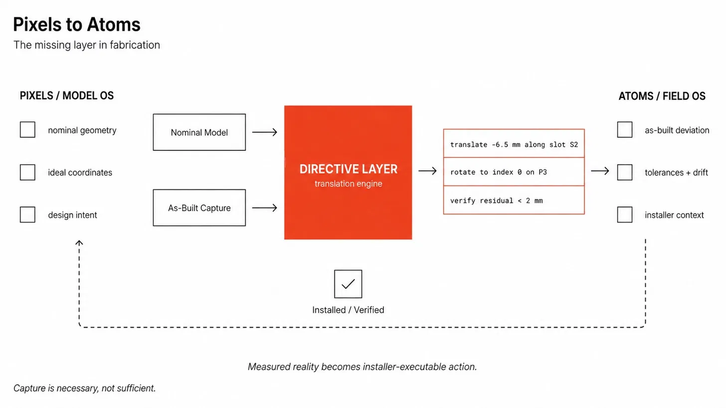
This is a structural problem, not a quality problem. The model and the field run on different operating systems. The model OS speaks in nominal coordinates, ideal geometry, infinite precision. The field OS speaks in deviations, tolerances, drift. The two systems don’t share a vocabulary, so every translation between them costs time, costs material, costs someone’s afternoon.
Somebody has to do the translation. Today, that somebody is usually a human: an engineer, a foreman, the crew themselves, working with paper and intuition and a calculator. The translation works, but it doesn’t scale, and it doesn’t compose, and nobody gets to use it twice.
The layer that does the translation is missing. That’s what this post is about.
The translation problem
Most of my work in this space has been at A. Zahner Company. Zahner makes architectural metal. The kind that ends up on museums, civic buildings, occasional aerospace work, and the very specific subset of buildings where the architect wants the cladding to do something complicated. The work means living inside the model-vs-field translation problem on every job, because Zahner’s panels are usually unique, fabricated to tolerances tight enough that field deviation matters, and installed in places where you don’t get to re-do anything.
Most people think the bottleneck is capture. That if you could just scan everything more accurately, the problem would go away. This is true in the narrow sense that capture is necessary. It’s not true in the broader sense that capture is sufficient.
Capture solves: where is reality, in coordinates I trust?
Capture doesn’t solve: given reality, given the model, given the part that’s about to be installed, what is the specific thing the installer should do?
That second question is the translation problem. Capture gives you a point cloud, or a survey, or a deviation map. None of those are directive. None of them say “rotate this panel three degrees about the upper-left bolt before you install it, and the holes will line up.” The translation from observation to action is its own layer, and that layer is mostly missing from current AEC tooling.
A scan tells you the wall is eight millimeters off. It doesn’t tell you what to do about the panel. A deviation map tells you the panel is rotated 1.4 degrees from nominal. It doesn’t tell you which bolt to torque first.
A directive tells you: translate −6.5mm along slot S2, rotate to index 0 on P3, verify residual under 2mm.
That’s the missing layer.
What I built
I’ve been working on a version of this. It’s called Directive Engine. MIT-licensed, runs in a browser, accepts nominal geometry and as-built scans (point clouds in PLY or XYZ, or pre-aligned pose data), and emits directive cards: translate −6.5mm along slot S2, rotate to index 0 on P3, verify residual under 2mm. The math is real and unit-tested. The fixture in the demo is synthetic because I built it on personal time without access to a customer’s data, but the primitives generalize. It’s a 0.2 demo, not a finished product.
The demo walks a synthetic facade through five beats: detection (panels glow yellow or red where as-built diverges from nominal), constraint (the engine surfaces the part’s named features: slots, joints, indexed bolt patterns, so the directive lives in physical-feature vocabulary rather than abstract axes), directive (the engine emits the correction in installer language), apply (the panel animates to its corrected pose, status flips from pending to ok), and verify (before/after metric, pass/fail). Ninety seconds end to end.
The directive language is the part that matters most. A directive that says “translate 3mm in X, rotate 0.4 degrees about Y” is technically correct but operationally useless. An installer doesn’t have axes to translate along, they have slots and bolts and pivot points. The engine matches the corrective transform against the part’s declared kinematic features and writes the directive in their vocabulary. P3 is the panel’s four-position bolt pattern. S2 is its lateral mounting slot. J1 is its pivot joint. The directive composes physical features the way the installer composes physical actions.
Verification closes the loop. After the directive is applied, the engine recomputes the residual against the constraint envelope. If it’s under tolerance, the directive passes. If not, the directive is wrong, or the constraint was wrong, or capture was wrong. The pass/fail isn’t decoration. It’s the feedback loop that distinguishes a directive engine from an open-loop suggestion box.
The demo is at directive-engine.vercel.app. The case study at systemsforge.build/work/directive-engine includes a CLI invocation a reader can run against their own point cloud. The source is at github.com/barnes-ngb/directive-engine.
On capture
The demo’s facade is synthetic. Capture is well-trodden in AEC: laser scanning, photogrammetry, robotic total station survey. I built one version of that capture problem at A. Zahner Company: SurveyLink, peer-reviewed in Taylor & Francis 2022, which streams data from a total station to a web-based 3D model in real time, comparing each measured point against the corresponding target plane so installers see live deviations against the as-designed geometry. The layer underneath all of those capture methods is where the floor was empty: translating the deviations they produce into installer-executable directives. That’s what Directive Engine is.
SurveyLink runs at the panel scale and gives the installer per-interface guidance. Directive Engine sits underneath, at the scale where deviations have already been measured, and writes the action. The two are complementary; neither replaces the other; both can use the same captured reality as input.
Under the hood
The engine uses Horn’s method for rigid alignment, PCA line fitting for pose recovery from sparse measurements, quaternion algebra for rotation handling, and a small clamping and quantization layer that snaps continuous corrective transforms onto the discrete envelopes (slots, indexed bolt patterns) that the part’s geometry actually allows. None of this is novel. These are textbook 3D math primitives. What’s novel is the layer that translates between them and an installer’s working vocabulary.
The unit tests cover all of it. 188 tests at last count, running against synthetic point clouds derived from the demo’s fixture. The end-to-end test takes a PLY file, runs it through the parser, runs the points through segmentation and PCA, recovers the per-part pose, computes the directive, and asserts the directive’s translation vector matches the known synthetic offset within 0.5mm. The math chain works on the input format real scans produce.
It’s a 0.2 demo, not a finished product. Pose recovery returns identity rotation; rotation directives come from constraint quantization, not line-fit residuals. Only ASCII PLY and XYZ are supported; binary PLY is the natural next layer. One defining line per part; multi-feature parts need to be decomposed. These are scope decisions, not bugs. The math chain that would close each gap is mostly already in the codebase; what’s missing is the specific extraction or reader at the boundary.
The demo says 0.2 because that’s what it is. It runs. It produces sensible output on the inputs it accepts. It’s a worked example of what the layer looks like, not a product I’d ship into a production fabrication shop.
The pattern probably shows up elsewhere
The structure of the problem — two operating systems with different vocabularies, a missing translation layer between them — isn’t AEC-specific. It shows up anywhere precision design meets imprecise reality.
Aerospace tooling has it. Composite layups against a master mold need to be measured and reconciled. The mold drifts. The part drifts. The fixture drifts. Somebody writes the directive that brings them back into agreement.
Manufacturing assembly has it. Robotic arms work to nominal poses; the parts they pick up have manufacturing tolerances; the fixture they place into has wear. Somebody (usually a human, sometimes a vision system) writes the corrective directive that bridges the two.
Surgical robotics has it, at much higher stakes. Preoperative imaging gives nominal anatomy. The patient on the table has shifted, breathed, deformed since the scan. The surgeon, or the robot, operates against reality, not against the image. Directive translation is what makes the registration robust.
I’m not claiming Directive Engine works for any of these. The math primitives transfer; the operational vocabulary doesn’t. An aerospace technician doesn’t think in “slot S2.” They think in their own physical features, their own indexes, their own tolerances. The directive layer would have to be rewritten for each domain.
But the structural diagnosis is the same. The model OS and the field OS speak different languages. Somebody has to translate. The cheapest place to put that somebody is in software, where they can compose, where they can be tested, where they can run when nobody’s watching.